Page 2
This assembly guide describes how we assemble and mount modules and boards, such as the DECUS and AGEN Modules, the AGEN Test/Programming Board and the MUTS Module. The guide also applies to products that are furnished as raw printed circuit boards or kits that require customer assembly. The intent of this guide is not to give step by step assembly instructions but to provide information and techniques that may help assemble projects using our products.
Most of our products are furnished assembled and tested. However, products such as the AGEN and MUTE Target Boards are assembled to meet unique project requirements.
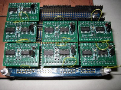
Assembly is normally not difficult because all Target boards have their components labeled on the silk screen or marked in copper. Additionally, each board has a schematic and parts list to help clarify board wiring, component specifications and parts placement. To expedite assembly, inspection and test, we often use assembly and test fixtures such as the one shown at the top of this section. The photo above shows a number of DECUS modules that have been assembled together. A separte test fixture is used to test each DECUS module.
Page 3
When assembling boards, we start by rubbing the top and bottom board surfaces with a soft cotton cloth to remove any residue that may have accumulated in the manufacturing process.
It is important to hold the board horizontally in a secure position and to provide good lighting and magnification during assembly.
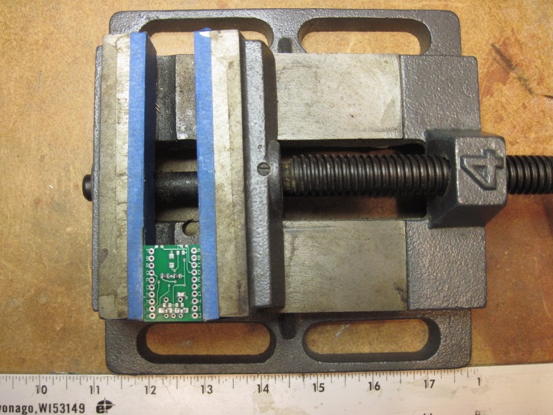
The board can be held in position by gently clamping it in a drill-press vice, as shown in Photo 1. We have found this kind of vice ideal for PCB assembly because it is heavy and securely holds the work near the workbench surface. Vice-mounted boards can be easily positioned by moving the vice on the workbench surface but, once the vice is placed in the working position, the board will not easily move if the vice is accidently bumped. As shown, the vice jaws can be covered with masking tape to somewhat isolate the board from metal vice jaws and lead screw lubricant.
Once the board is securely positioned, parts can be accurately placed on pads using an illuminated magnifier mounted on a spring-loaded swing arm above the vice. A magnification of 2 to 4 times works well. Parts can be placed with tweezers; curved-jaw tweezers seem to work best for us.
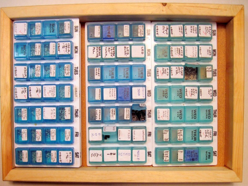
As shown in Photo 2, parts can be easily stored and accessed during assembly using flip-top pill containers. Labels can be applied over the top of the "MTWTFSS" markings to identify contents by type, value and size. Although most of the bins in the photo are labeled along the short edge of the label, we have since found that labeling along the long side is easier and more legible.
We find that it is best to first separate the parts by size (e.g., 1206, 0805 or 0603) and then by type (e.g., resistors, capacitors, diodes/transistors/arrays). Most pill compartments can hold a dozen or so SOIC packages and several hundred discrete SMT parts such as resistors, capacitors and component arrays. The compartments are also useful for storing programmed chips -- a batch of chips can be programmed and stored in a marked compartment before chips are needed for module assembly.
Page 4
We recommend mounting the bottom side parts first because this is typically where we mount most of our small discrete SMT parts. Some schematics, such as the ATAR Target Schematic, provide a layout of the pads on the bottom of the board to help in component placement. If a large number of parts mount on the bottom of the board (e.g., the "pinking" network for AGEN), the bottom of the board can get very "busy." In most cases an accurate placement guide should be nearby before starting board assembly.
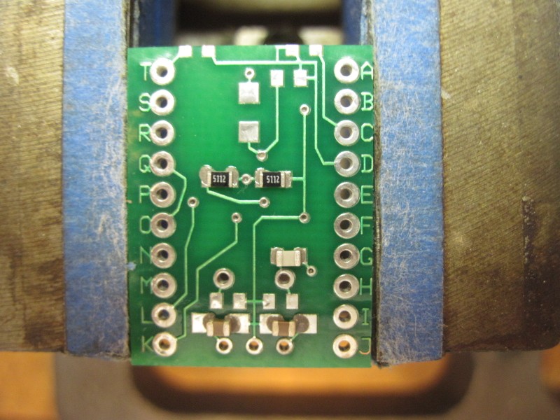
Starting with the bottom side is somewhat arbitrary, but it is suggested here primarily because the greatest amount of heat is generated when applying hot air to SMT parts distributed over a large area. Photo 3 shows some SMT resistors and capacitors placed on the bottom of a board with the pads coated with solder paste.
Mounting the microprocessor or larger parts on the top of the board is a good way to complete the assembly because less heat is transferred through the board to the bottom components. The heat applied to the top of the board is generally confined to the area near the chip(s) and the board surface is somewhat shielded by the chip bodies. But, first mounting top side parts will also work in most cases.
After mounting the SMT parts, the next part to be mounted should be the crystal (if used). Note that there may be a small via on some boards near the crystal. We recommend mounting the crystal slightly above the board to avoid touching any vias. This can be easily done by holding the crystal about an eighth of an inch above the board while making sharp bends on the leads projecting through to the bottom of the board. Another way to keep the crystal spaced above the board is to press it down on a toothpick while bending the leads on the bottom of the board -- this ensures even mounting while keeping the crystal leads short.
Page 5
Next, mount the regulator (if used). If the regulator is not used, install a jumper between the input and output pads for the regulator, being careful not to short the jumper wire to the center (ground) pad. Usually, a curved bare wire is sufficient to loop over the center pad. This also provides a convenient test point for the voltage applied to the module. When installing the regulator, carefully position it according to the silk screen marking. The 78L33 regulator pins are different from the "normal" regulator pin sequence: as you face the 78L33, the input to the regulator is the rightmost pin.
After the regulator, mount any parts that do not have plastic coverings or carriers. These would include any parts with leads, such as zener diodes or special resistors.
The last parts to be mounted should be those that contain plastic or other heat sensitive materials. These parts would include plastic-covered trimmer capacitors, discrete electrolytics covered with plastic, shrouded connectors and stake pins. Mounting these parts last avoids melting the plastic parts with hot air during the SMT assembly. If you need to apply hot air to the board after these parts are mounted, damage can be minimized by masking the parts off with damp masking tape or cardboard. Do not use metal shields because they tend to heat up and transfer heat to the part.
To keep long rows of stake pins straight, push them into socket pins. For example, when assembling an AGEN Module, push the edge pins into the socket pins of the AGEN Test/Programmer Board before fitting the board to the stake pins. It also helps to run a solder flux pen over the exposed tops of the pins before placing the board and soldering -- this makes the solder form a more even "cone" around the pin. Stake pins can be soldered with a small-tip soldering iron and thin rosin-core solder. After soldering the pins, scrub the board with alcohol to remove most of the rosin flux. This scrubbing also removes solder spall from between the pins of the chips and next to the bodies of small SMT parts such as resistors and capacitors.
Page 6
Small stake pin jumpers and IDC connectors can be installed straight and flush to the board by temporarily holding the part on the board with masking tape and then solder-tacking a corner or end pin to temporarily hold the part on the board. The part can then be mounted flush and vertical by positioning it by hand while re-soldering the tacked pin. Once the body is positioned correctly, the remaining pins can be soldered. If berg jumpers are to be installed on jumper pins, install them before soldering the part to the board to help hold the pins in alignment in the event that the heated pins move in the plastic carrier.
Page 7
Like techniques used to solder with a soldering iron, it seems that everyone has a favorite method that works best for them. For hot air soldering, what works best for us is to apply small amounts of solder to individual pads or a bead of solder across a row of solder pads. Solder application is easiest with a syringe fitted with a small-nozzle needle.
We had to try several nozzles from an assortment to get the right one. If the paste doesn't squeeze out in small enough increments the nozzle can be gently squeezed to reduce its size, but this is less satisfactory than using the correct size nozzle. It is much easier to correct problems with additional solder than to deal with excess solder applied from an overly-generous nozzle. We have found that the nozzle supplied with most solder syringes is slightly too large for use with our techniques.
If processor pins or other SMT components are shorted due to excess solder paste, the short can be removed with a small-tipped soldering iron and a piece of copper braid coated with solder flux (e.g., flux wiped on the braid with a flux pen or a brush dipped in a bottle of liquid flux). Apply the treated braid and soldering iron tip on the short, which is typically near the chip body.
Individual pins that do not have an obvious solder connection can be re-heated with a small-tipped soldering iron. Re-application of solder paste or the use of conventional solder is seldom necessary and is only needed for pins that are obviously too "dry."
When using solder paste and a soldering iron, it is common to get small solder balls outside the pad areas; these may only be visible under high magnification and must be removed before deploying the board. If it is necessary to re-mount a component, heated flux-soaked braid can be swiped across the mounting pads to remove any excess solder prior to re-pasting the pad(s).
Page 8
We have used a number of types of solder paste with good results but now use "No-Clean 63Sn/37Pb", part SMD 291AX, solder paste from ChipQuik®. With this paste, we use hot air at a temperature of 350-360 degrees F. We also use ChipQuick low-temperature, no-clean, tack flux (Mouser part 910-SMD291) to help re-solder and rework chips, but this is seldom needed. ChipQuik® low temp lead-free SN42/Bi58 solder paste, part number SMDLTLFP, also works well and uses a much lower hot air temperature (281 degrees Fahrenheit, 130 degrees Celsius). ChipQuik® generally supplies excellent SMT soldering tips with each syringe of solder.
Although the flux in the solder pastes that we use appears to be water soluable, we normally scrub the board with a denture brush and denatured alcohol. We use the denture brush because it has large heavy-duty bristles and is readily available. One customer observed that scrubbing boards with nylon bristles may cause a static problem, we have had no failures from our cleaning process. This is probably because the boards are covered with fluid during the scrubbing process. The alcohol scrub removes some of the rosin flux for parts mounted with a soldering iron and rosin core solder such as the crystal, regulator, leaded components, IDC connectors and stake pins. We do not recommend tempting fate by dry scrubbing the board with a nylon-bristle brush.
According to several Internet sources, excess flux probably does not need to be removed and this seems to be the case from observing some commercial boards. Thus, our scrubbing process is probably more cosmetic than functional. But, we have noted that scrubbing generally needed to remove spall left between parts and pins (e.g., during re-work with an iron and solder paste).
Scrubbing with water is somewhat effective for removing water soluable solder paste but washing or scrubbing is most effective soon after parts are mounted and when heated water is used. When a water rinse is needed, we use a microwave oven to heat a shot glass filled with distilled water. Some recommend using a very small amount of detergent in the water with a thorough rinse afterward. We have not tried this technique.
Page 9
There are a number of excellent SMT soldering guides on the Internet (e.g., ChipQuik® site)). These often show short video clips of the SMT soldering process. We recommend looking at a number of sites and assimulating the collected (and sometimes contradictory) wisdom offered there. Our intent is to tell you what we do and what has worked for us during the assembly of hundreds of boards but there are a large number of equally effective techniques that may suit you better.
After a board has been assembled and cleaned, it should be inspected under a high-magnification loupe. We use a 30 power loupe. A loup with this high a magnification is somewhat difficult to find, but we have found that lower magnification loupes are not as good for close inspection.
It is not uncommon to find small solder balls (spall) between microprocessor pins, even after scrubbing. These should be removed with additional scrubbing and inspection. As mentioned above, some chip pins that are not obviously soldered well can be fixed with the brief application of a small-tipped iron. When doing this, first try re-heating. If additional solder is required we normally used a small dab of solder paste instead of roll solder. The paste does not load the pin up with solder but may create small solder balls that must be removed.
We have found that 0803 parts are the easiest to deal with for typical hobby projects. The 0603 parts are not much more difficult to use but our boards are generally not that cramped for space (forget 0402 parts, life is too short). We use some 1206 parts mostly because we have reels of them on hand. The biggest problem with 0603 parts (and sometimes 0803 parts) is that they tend to flip on end during hot air soldering.
Flipping can be minimized by pressing the components down on their pads after placing them with tweezers and before applying hot air. Other contributing factors to the flipping problem are uneven application of heat across the part body and excess solder paste on the pad (or a solder paste differential between pads). In any case, the best way to deal with a flipped part is to keep a dental pick handy so that the part can be pushed over while the solder on the pads is still molten.
Page 10
Finished modules assembled with rows of stake pins on their board edges, such as AGEN and MUTS, can be plugged into a solderless breadboard or mounted directly on a sea of holes breadboard with 0.1 inch spaced solder pads. For our in-house projects we typically mount rows of in-line sockets on vectorboard so that a module can be easily removed for reprogramming and during motherboard wiring. Our favorite Proto Board is a 3" X 4" board available for about $5 from Parallax, Inc.. This board is somewhat difficult to find but you can go directly to it by entering the product code "45304" inter the parts search dialog on the home page.
Other than custom PC boards, our favorite mounting technique is to use point-to-point wiring between solder pads with Kynar wire-wrap wire.
Wiring pad-to-pad with wire wrap wire is somewhat "old school" nowadays, but it provides secure connections that can be easily changed for flexible project development. This technique also provides reasonably good high-frequency performance and, if done correctly, is extremely reliable in long-term service.
The biggest problem with this kind of wiring, other than being somewhat slow and "fussy", is that connections may be unreliable if there is insufficient solder on a pad. This can cause wires to appear soldered when they are just stuck on with flux. Also, wires attached to poorly "wetted" pads can pull loose. We recommend applying a liberal amount of solder to each pad before trying to attach a wire end; the solder should form an even cone between the pad and the socket pin. If you need to attach multiple wires to a pad, it is often advisable to use multiple pads and connecting jumpers rather than trying to hold multiple wires on a pad during soldering.
Page 11
For gluing assemblies together, we mostly use a product named "E-6000®", although there are other products that are similar. This glue is commonly available and is typically found in craft stores, hardware stores or TAP Plastics (small tubes and caulking tubes). This glue dries clear and is very flexible. Other colors are available, including UV resistant black for outdoor applications.
E-6000® provides a secure bond to almost any combination of surfaces, but glued items can be pulled apart, if necessary, even after a year or so of drying. The glue dries somewhat slowly, but sets up to a usable consistency in less than an hour. But, glued items should normally be left undisturbed for 8 hours or more to provide the most secure bond. Any excess glue can be trimmed with a sharp blade and pulled off cleanly. Excess glue (e.g., at the edge of a panel) can also be rubbed off, much in the same way as rubber cement. The glue is also paintable and photo safe and is thus ideal for attaching panel labels (another favorite use). It can also be used as very low loss "coil dope" and can be thinned with MEK.
As an example of how E-6000® can be used to mount boards, look at the Test/Programming platform for AGEN shown in Photo 5. The board is mounted on the top of a small breath mint tin. After the board was assembled, four nylon standoffs were glued to the corners of the board with E-6000@reg and left for several hours. Note that, while drying, E-6000® is somewhat fluid -- parts should be kept level or held in place with masking tape until the glue sets (about 15 minutes). Examine your glue-up a short time after gluing to ensure that parts have not slid out of place.
Once the standoffs on the AGEN Test/Programming board were securely glued to the board, the bases of the standoffs were glued to the top of the tin. To provide a stable platform that doesn't move around on the test bench, the tin was filled with BBs. Miscellaneous junk nuts and bolts would also serve to weigh the tin down. The top of the filled tin was glued shut with a dab of glue. To provide more stability for the tin base, the bottom of the tin was slathered with a thin coat of E-6000®. When it dries, the consistency of E-6000® is similar to rubber and thus provides an inexpensive non-slip surface. The label on the tin was also glued on with E-6000®. Too much of a good thing is just about right.