Except for serial and programming pins, all DACS I/O appears on the main I/O connections on one side of the board. Quick connections to these can be made by installing stake pins on the connector holes and plugging the board into a solderess breadboard.
More permanent connections can be made by inserting the stake pins into a 1x28 socket mounted on a carrier board. The socket pins can be soldered to wires or connectors to provide connections to project hardware.
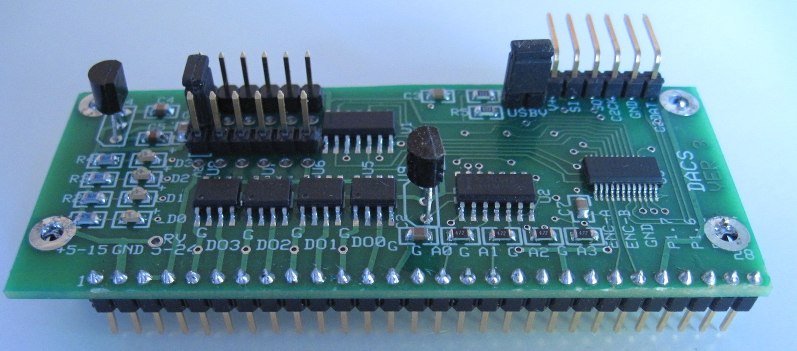
This application note describes how to bring out the DACS I/O to stacked screw-down terminals. This stacked I/O scheme uses a DACS board with stake pins installed on the I/O edge connections, as shown in Photo 1. This allows the board to be removed from a breadboarding configuration to a permanent wiring assembly without changing the DACS I/O connector. The stacked terminal connections provide permanent, compact and flexible connections to your project.
Photo 1. DACS with Stake Pin I/O
Page 2
The stacked terminals are supported on a small motherboard that, on one end, connects to the DACS stake pin I/O and, on the other end, provides terminal connections for DACS I/O. The Motherboard was built with a small prototyping board with a 6x28 hole pattern.
The motherboard also mounts a 1x28 socket that connects to a "mezzanine" board (Mezzanine Board) that sits just above the Motherboard terminals. The stacked I/O assembly provides screw-down connection points for all DACS I/O. The following sections show photos of the stacked I/O assemblies and provides construction details and options.
The DACS stake pins plug into a 1x28 socket on the Motherboard. Photo 2 shows the Motherboard. The DACS stake pins fit into the socket row nearest to the back edge of the board (i.e., the socket at the top of the photo).
In this particular implementation, the terminals mounted on the Motherboard bring out the outputs and inputs. The four outputs and two ground terminals are on the left of the photo. The six inputs and two ground terminals are on the right of the photo. Ground terminals are marked with a permanent marker.
Photo 3 shows DACS mated to the Motherboard.
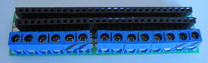
Photo 2. Motherboard
Page 3
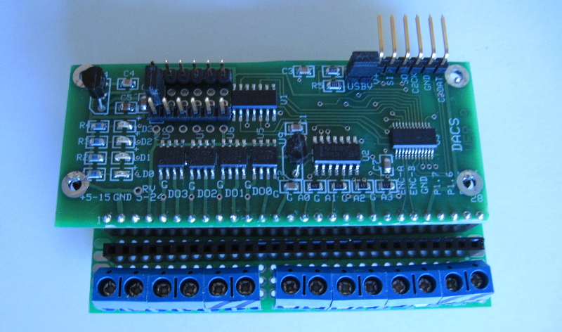
Photo 3. DACS Mated to Motherboard
Page 4
The 1x28 socket in the middle of the Motherboard provides connections and mounting for the Mezzanine Board. The Mezzanine Board mounts above the Motherboard terminals.
Photo 4 shows the Mezzanine Board with stake pins installed on one edge and terminals installed on the other edge.
As shown in Photo 5, the Mezzanine Board plugs into the Motherboard so that its terminals appear just above the Motherboard terminals.
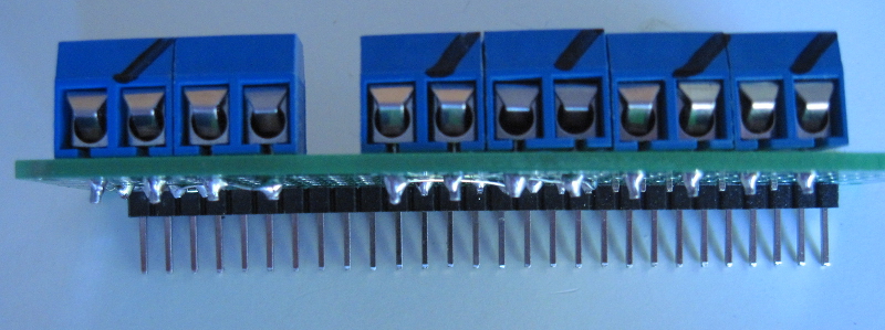
Photo 4. Mezzanine Board
Page 5
Photo 5 shows the final assembly with the Motherboard and Mezzanine Board connected together and mated to the DACS board.
The Mezzanine Board's terminals bring out the connections for the the Vdd and RV power inputs (on the left of the photo). The four analog inputs are brought out on the group of eight terminals on the right of the photo. As with the Motherboard terminals, ground connections are marked with a permanent marker.
Wiring to the Motherboard and Mezzanine Board terminals is performed on the bottom of the Motherboard. Connections from the DACS socket are wired directly to the Motherboard terminals or brought up to the Mezzanie Board by wiring to its Motherboard connector. This provides a great deal of flexibility in how the terminal groups are brought out and wired.
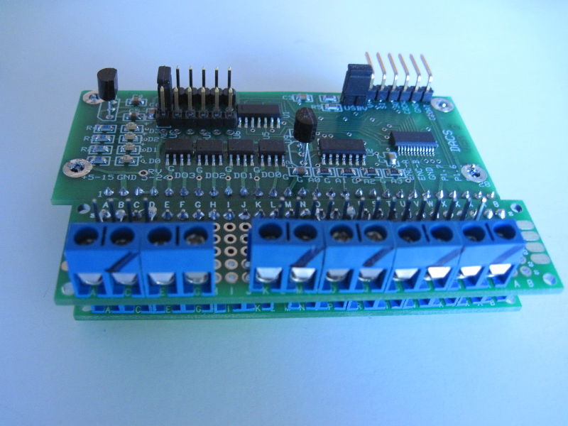
Photo 5. Assembled Mezzanine I/O
Page 6
Initial Release |
Copyright © June 1, 2014, Bob Nash.