Many of our products require a serial communications interface. The serial interface is typically used to issue commands to a module, either from a terminal program or from a Host controller such as a PC, Raspberry Pi or microprocessor-based controller.
The following shows how to connect a serial link to a product board and how to configure and test a terminal program for manual operation.
This note also describes the BOBI interface used by many of our products. It shows how to connect the interface to power, serial hardware and a programmer.
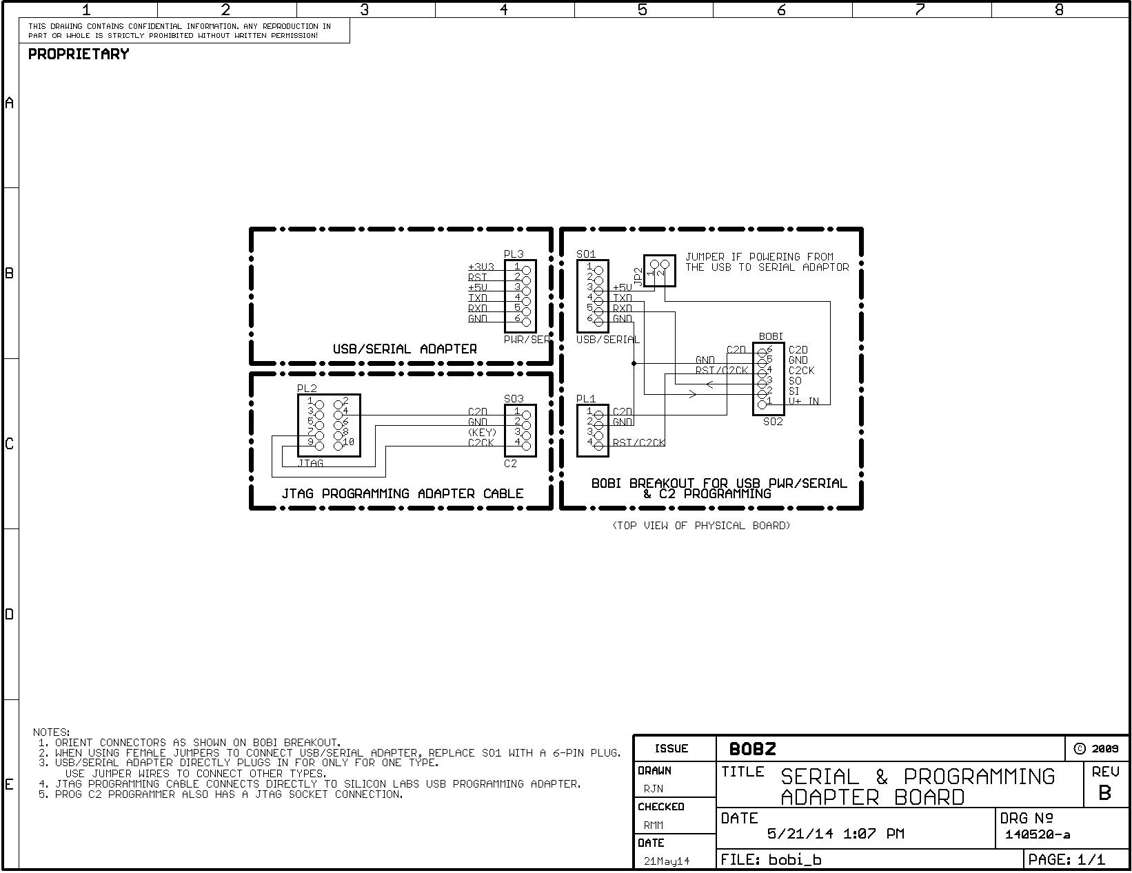
Connection to both a serial interface and a programmer can be performed easily with our BOBI Breakout (BIB) board. This note provides a schematic of the breakout board and shows typical serial and programming connections.
Page 2
The BOBI interface provides a convenient and consistent way of connecting power, communications and programming devices to our products.
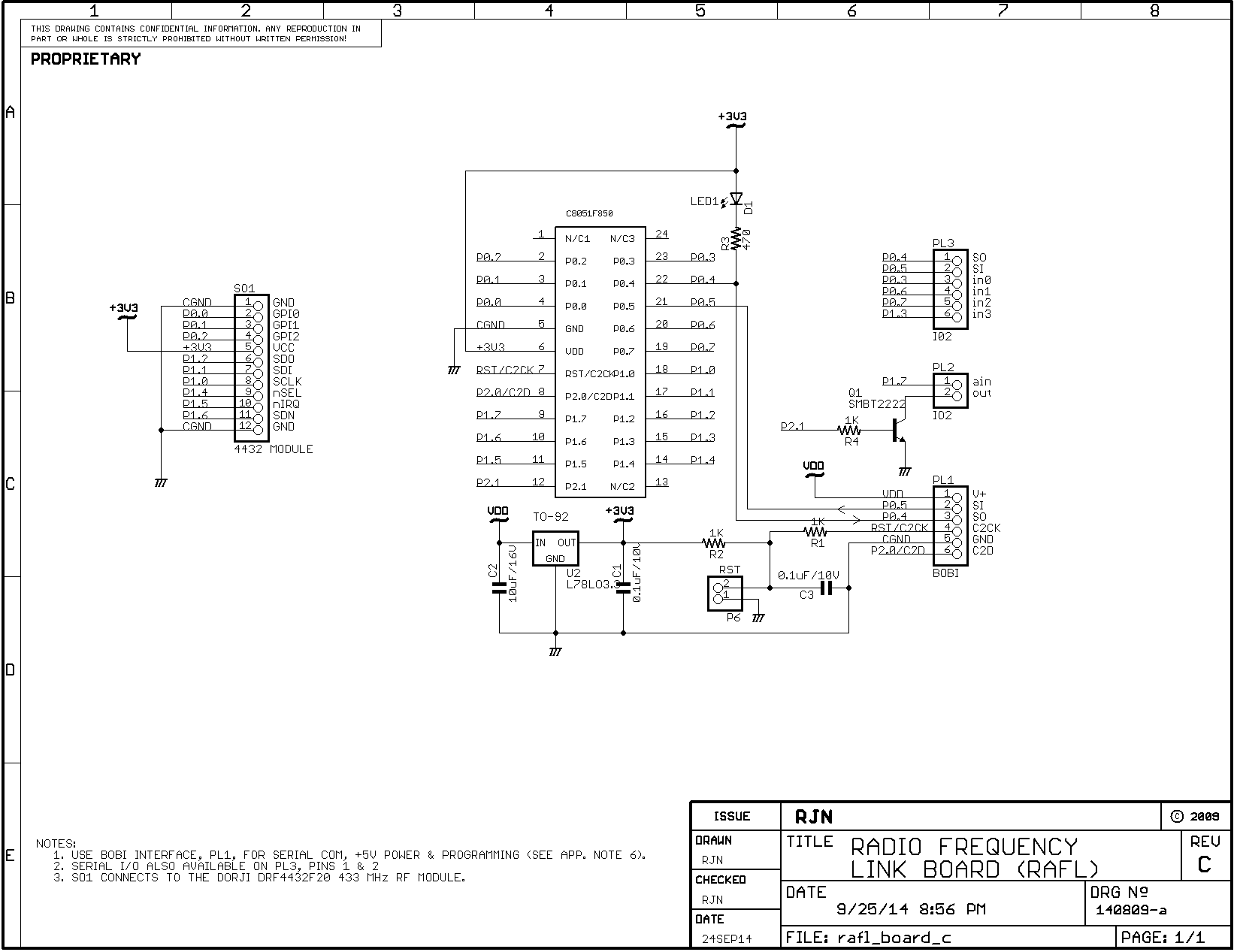
Schematic 1 shows connections for a typical product, the RAFL Radio Frequency Link module. The BOBI connector is designated "PL1" on the schematic.
Power for most products can be applied between PL1, pin 1 (PL1/1) and ground (PL1/5). The positive voltage input to the BOBI interface is labeled "V+" on the silk screen and is typically +5 Volts from a USB to serial adapter.
The ground is labeled "G", "GD" or "GND" and is the reference for the power and the serial interface. Power options and connections may vary by product and are beyond the scope of this document.
The serial input, labeled "SI", connects to pin 2 of the BOBI interface (PL1/2). The serial output, labeled "SO", connects to pin 3 (PL1/3). The programming connections are labeled "CK" or "C2CK" (PL1/4) and "C2D" or "C2" (PL1/6).
The serial input and output designations are "board centric" and refer to on-board processor's serial input and output pins. Direction arrows on the schematic show the serial data directions. Thus, the TTL-level serial output from a terminal would drive the "SI" pin and the "SO" pin would drive the TTL-level input of a terminal connection (e.g., via a USB adapter).
The programming pins are designated "C2CK" or "CK" (PL1/4) and "C2D" or "C2" (PL1/6).
The programming connections allow programming the chip in-place using the Silicon Laboratories C2 protocol. The programming pins normally connect to the programmer described in the MIDE (MyForth IDE) documentation.
With a simple socket adapter, the programming pins can directly connect to the Silicon Laboratories IDE through a Debug adapter.
Page 3
Page 4
Page 5
A USB to serial adapter based on the Silicon Laboratories CP210x chip is normally furnished with each module requiring a serial interface. The adapter connects to a Windows or Linux PC to establish a serial link.
Using the serial adapter with a terminal or programming script requires connecting it to a USB port and configuring the port to operate with the adapter.
The pins on the BOBI connector can be broken out to allow simultaneous connection of a USB adapter and a programmer. This breakout is performed with a BOBI breakout (BIB) board. Schematic 2 shows how the serial and power connections from a USB to serial adapter connect through a BIB breakout board. Also shown is how a programmer connects through the BIB breakout board to the project board. Operation and connection of the programmer is also described in the MIDE (MyForth IDE) documentation.
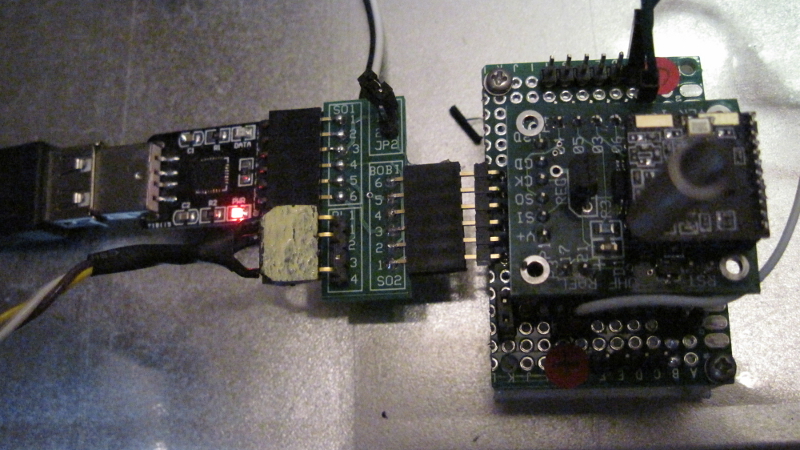
Photo 1 shows a USB to serial adapter connected through a BIB board to the BOBI interface on a RAFL module. The photo also shows a programming cable connected to the BIB breakout.
Photo 1. Serial Connections to a RAFL Controller
Page 6
Page 7
Page 8
Modules can directly connect to a USB to serial adapter with three socket-to-socket jumper wires. Modules are normally tested with the USB to serial adapter that we furnish. After testing, the serial connections between the adapter and the module are left in place and shipped with the correct connections. We recommend noting the connection pins and color coding of the shipped module before disconnecting them.
But, wiring can be reconnected without reference to the original connections by observing the data sense arrows shown in Schematic 1 and noting the designations on the adapter.
Most adapter I/O labels are "board centric" in that outputs are from the board and inputs are to the board. As noted above, this is the convention we use. Thus, an adapter connection labeled "TXD" is most likely the transmit data output from the adapter. If this is the case, it would connect to pin 2, "SI" (serial input) of the BOBI connector.
If your serial connections do not work, try reversing the wires at one end. Although we are obligated to warn that improper serial connections can potentially damage hardware, we have mis-connected several adapters, including the direct serial connection to the Raspberry Pi, without damage.
Once the USB adapter connections are established, the adapter must be configured before it can be used.
Windows systems generally require installation of the "virtual comm. port" (VCP) serial driver. This can be downloaded at the Silicon Laboratories site.
The site also provides several application notes that discuss the operation and installation of CP210x drivers on Windows systems. The most applicable is AN335, titled "USB Driver Installation Methods." This discusses installation on various types of Windows systems, including XP. Detailed explanation of how to install drivers on Windows systems is beyond the scope of this manual.
Linux systems are somewhat easier. The USB-based serial connection is usually automatically configured when the adapter is plugged in. But, to configure a terminal program or use the serial port with a script, it is necessary to determine the device mapping.
Serial device mappings vary between Linux distributions but our PC running Debian maps the first device as: /dev/ttyUSB0. Unless you have other USB to serial adapters attached, this is the most likely the adapter mapping.
To find serial device mapping, use a command: dmesg | grep "ttyUSB" or dmesg | grep "tty" at a command prompt. This shows all startup serial (tty) mappings but may not show mappings due to USB connections afterward.
Page 9
The following section describes direct serial connections, including connection to a Raspberry Pi. Note that a USB connection can also be used with the Raspberry Pi and Beaglebone Black.
Our development system uses a Raspberry Pi wired to a USB hub that connects two USB to serial adapters to our modules. We use the direct serial connection to communicate with our programming module.
The serial data link can be implemented with a direct connection to a hardwired TTL-level serial port such as that available on the Raspberry Pi.
A direct serial connection to a hardwired port that operates at true RS-232 voltage levels requires a TTL to RS-232 adapter. These are inexpensive and commonly-available. These RS-232 adapters are discussed in the documentation for our DCON (DDS Controller) product.
For direct TTL-level serial connections or connections to the TTL levels provided by an RS-232 adapter, connect the TTL data output to the "SI" pin and the TTL data input to the "SO" pin.
The direct Raspberry Pi serial I/O connections to the BOBI interface are as follows:
If you are not sure of the Pi pin numbering, there are a number of pictorials on the internet that show it. The single hardware serial port on the Pi maps to the "/dev/ttyAMA0" device. USB to serial adapters can also connect to the Pi to provide additional serial ports.
When using USB to serial adapters, the Pi is typically connected to a USB hub for USB connector expansion and power isolation. The USB adapters map and connect as described above in the section on USB to serial adapters. For example, our Raspberry Pi adapters map as "/dev/ttyUSB0" and "/dev/ttyUSB1", thus providing two additional serial ports.
Page 10
Once the serial connections are wired and the device or the "com" number is known, install a terminal program and configure it for the product's serial parameters.
Any terminal program such as Hyperterm, Procomm, PuTTY (Windows and Linux), or minicom (Linux) should work. For Windows, we like PuTTY. For Linux, minicom is a good choice because it is often pre-installed.
Configure the terminal program by setting the device (Linux) or "com" number (Windows). Presently, our products all operate at a baud rate of 19.2K with 8 data bits, no parity and one stop bit (8,N,1). Configure the terminal program to use these parameters. You may also need to disable local character echoing: most of our products echo serial characters.
When configured and connected properly, entering a command should elicit a response from the module. For example, entering a carriage return (or space) should produce a ">" prompt on all products.
When using minicom, we suggest starting it up initially from root and in the configuration mode (i.e., sudo minicom -s). This allows you to set the device and baud rate and save it to the default configuration file.
With minicom, you can also save the current configuration as a named configuration file. These are named "minirc.xxx", where the "xxx" is a name you supply. Configuration files are normally stored in a location such as "/etc/minicom" and can be specified as a command line parameter at startup.
For example, entering "minicom bob" at a shell prompt might be used to bring up minicom using a saved configuration file named "/etc/minirc.bob" specifying "/dev/ttyUSB0" as the serial port and configured for operation with our products.
There are many ways to to install a serial port and connect it to a terminal program for various hardware and software products. It is beyond the scope of this manual to describe all of the possible combinations. But, there are many detailed tutorials available on the Internet.
Page 11
If you need to confirm that the serial port is working with your terminal program, you can perform a hardware loopback test. To do this, connect the serial input and serial output pins together (e.g., the TXD and RXD pins of the USB adapter). Usually, this can be done with a socket-to-socket jumper wire.
Also ensure the terminal is configured for "no handshaking" (e.g., no RTS/CTS or XON/XOFF handshaking). Then, regardless of the other terminal settings, any character typed at the terminal should be echoed to the terminal's display. We recommend performing a loopback test before concluding that a module or a TTL to RS-232 adapter are not functioning.
If using a level converter you can also do a RS-232 loopback check by wrapping the transmit and receive pins at the RS-232 side of the converter (e.g., connect pins 2 and 3 at the DB-9 connector).
Many USB to serial adapters have an on-board LED to indicate data transmissions. This can be used without a loopback configuration to check that characters from the terminal are reaching the adapter (i.e., typing at the terminal flashes the LED).
Many of our products have a data indicator LED connected to the "SO" output. For example, see "LED1" on Schematic 1. The data LED can be used to verify that characters are reaching the board.
Once the product is working correctly, the data LED's current limiting resistor can be removed from the board to (slightly) reduce power consumption. In Schematic 1, this resistor is labeled "R3" (470 Ohms).
Page 12
Initial Release |
Copyright © November 2014, Bob Nash.