
The following describes the construction and operation of a DDS System board (DSYS1) that integrates the functions of a DCON DDS Controller module and one Direct Digital Synthesis module. The assembly provides an complete serial to DDS controller that easily integrates into DDS projects requiring a single DDS.
As shown in the two photos above, DSYS1 assembly is a two-board stack that consists of a DCON system board and a DDS module. The system board includes:
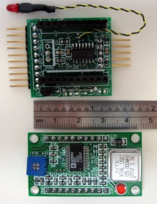
The DDS board is shown separated from the system board in the photo to the left. The photo to the right shows the assembly as shipped, with a DDS module plugged into the system board and with a USB to serial adapter. Also included in the shipment is a CD containing this documentation.
For off-line reference, you can download a PDF version of this manual.
Page ii
(BLANK)
Page 1
Page 2
The DSYS1 system assembly provides an integrated solution for users that do not want to manually wire a DCON DDS Controller to a DDS module and test it. The DSYS1 board consists of a DCON processor and interconnections to a socketed DDS module. Because the DDS module stacks on top of the system board, the entire DSYS1 assembly is very compact. This is illustrated in Photo 1, below, a closeup view of the DSYS1 assembly.
Also shown in Photo 1 is a USB to serial adapter shipped with each DSYS1 assembly. The adapter uses the CP2102 chip so that drivers are readily available. For applications where DSYS1 is connected to an RS-232 link, optional components on the system board can convert an RS-232 input to logic levels needed by the microprocessor.
As described below, the entire assembly can be brought up with only the addition of a few jumper cables. Photo 1 shows typical interconnections made with stake-pin socket cables. As shown, there are four connections to the USB adapter for 5 Volt power and serial data. The green and yellow connections are for the DDS output signal.
For the following, refer to Photo 1 and to Schematic 1.
For convenient reference and improved readability, we recommend that you download a high resolution DSYS1 schematic and use it for reference in the following documentation.
Page 3
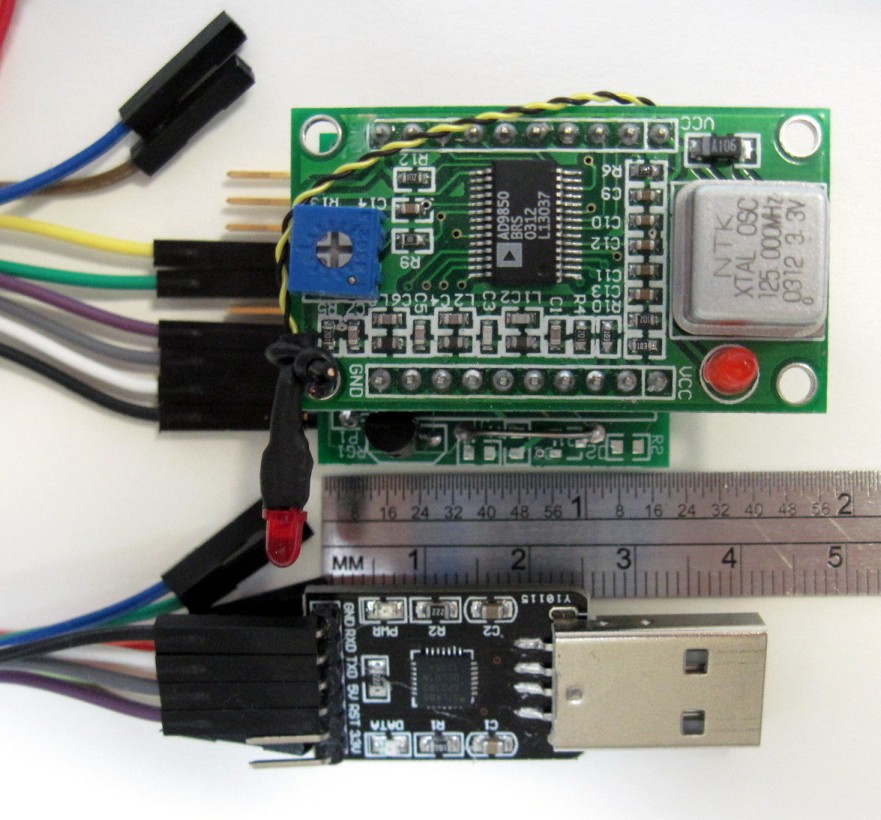
Photo 1 -- Closeup View of DSYS1 Assembly
Page 4
Most board connections are brought out to 10 pads on one edge of the system board. The board is shipped with stake pins soldered to these pads. Connections to external circuitry are typically made with jumpers having female sockets on one or both ends. The DSYS1 assembly is shipped with jumpers suitable for connecting the USB to serial adapter to the system board. Photo 1 shows the DSYS1 assembly connected to the adapter with these jumpers.
Alternatively, the pins can be inserted into a socket mounted on a prototyping board. The board assembly is shipped with right-angle stake pins soldered to the I/O pads, as shown in Photo 2, a closeup view of the system board without the DDS module.
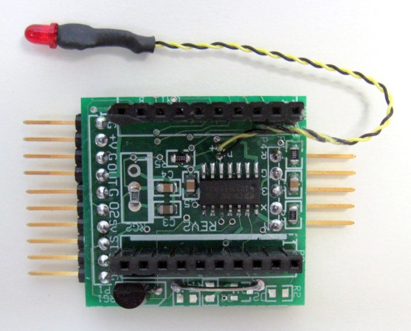
Photo 2 -- Closeup View of DSYS1 System Board
Page 5
Optionally, when the unit is ordered, you can specify the installation of straight stake pins so that the board can be installed on a breadboard socket or on a prototyping board. The board connections consist of:
The system board is also delivered with a 7 inch pigtal consisting of a pair of black and yellow wire-wrap wires. This pigtail is secured to the board with glue and can be routed to an LED error indicator to a microprocessor input. The DCON Documentation describes the use of this connection in more detail.
The DDS module mounts on a socket that straddles the microprocessor circuitry on the system board. There is no indexing or keying, but pin 1 of the DDS is marked with yellow paint on both the DDS module and the socket. The DDS module is factory-installed and normally does not neet to be removed.
Page 6
(BLANK)
Page 7
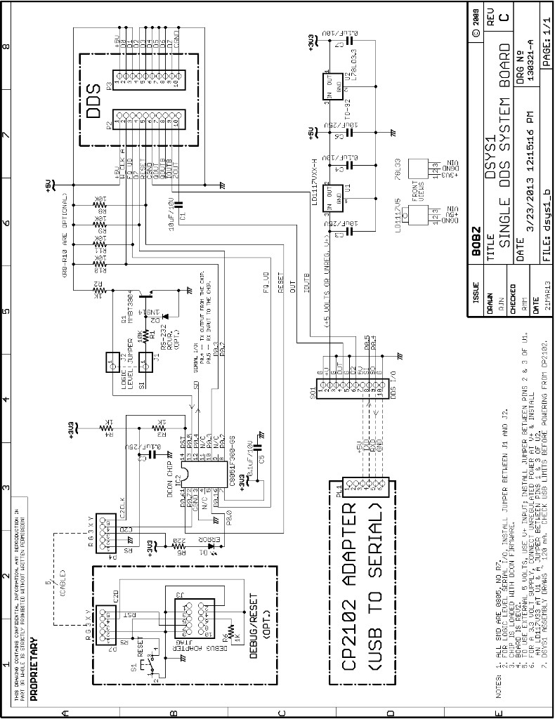
Schematic 1 -- DSYS1 Single DDS System Board
Page 8
(BLANK)
Page 9
The DSYS1 was designed to provide a more convenient format than using the DCON module and manually connecting it to a DDS module. The design objectives were to:
Page 10
(BLANK)
Page 11
The DSYS1 assembly can connect to a number of power sources, including:
The DSYS1 assembly is furnished with wiring for 5 Volt power from a USB adapter or from an external 5 Volt supply. This is factory-configured with a zero Ohm SMD resistor soldered across pads 2 and 3 of the LD1117 regulator footprint. Use of the board with other voltage inputs may require removal of this jumper and installation/removal of other board components, as described below.
The DSYS1 assembly can operate with a voltage higher than 5 Volts, provided that a LD1117V5 regulator is installed at U1. A 0.1 inch spaced pad footprint is provided on the system board for a LD1117V5 TO-220 regulator. The regulator is designed to mount under the system board, attaching to a heat sink or an insulated chassis mount.
Caution: the LD1117 pinout is somewhat unconventional -- see the schematic for connections. Take care with the device orientation when mounting to a chassis under the board -- some orientations will result in reversed connections.
To stay within the regulator specifications, the external voltage should be in the range of 6.2 to 15 Volts, although it is likely that voltages down to 6 Volts will work. The regulator has a current rating of 800 milliamperes which should not be a problem for the DSYS1 -- the assembly draws only 120 milliamperes, even with a high-frequency DDS output (e.g., 25 MHz).
The main concern is the power dissipation.
For example, with a 12 Volt input, there is a maximum dissipation of (12)(0.12) =~ 1.5 Watts. This would require some heatsinking of the TO-220 package. The maximum heatsinking required would be (15)(0.12) = 1.8 Watts.
At room temperatures and good ventilation, this dissipation can be provided by most small heatsinks or just about any chassis mounting. However, even a dissipation of approximately one Watt (e.g., a 9 Volt input) causes the regulator to become very hot. The regulator is protected against over-current and over-temperature but it is wise to install some heat-sinking for most applications.
Page 12
The board is configured for operation with a 5 Volt regulated supply. This is done by shorting pins 2 and 3 of the LD1117 footprint with a zero Ohm SMD resistor. Apply the external 5 Volts to pins 1 and 2 of the I/O connector. These are marked "+V" and "G", respectively. Normally, the ground return is connected to just pin 1, but any pins labeled "G" on the connector silkscreen can be used (e.g., pins 3, 5 or 10). When using an external 5 Volt supply, do not connect pin 7 to the USB adapter power. Optionally, regulated 5 Volt external power can be connected to pin 7, using any of the "G" pads for a ground return.
With the appropriate adapter, it is also possible to furnish power from a dedicated 5 Volt power adapter with a type A USB type connection on the adapter. These are typically used to charge cell phones. Use caution with these power adapters: some are poorly-filtered and depend on the battery load and filtering in phone to condition the output. We recommend checking these adapters under load (e.g., 50 Ohms) before using them with DSYS1.
The DSYS1 assembly draws about 120 milliamperes when the DDS module is operated at its highest output frequencies. The assembly can be powered from a USB adapter, provided that the USB power connection is capable of supplying 120 milliamperes. Most USB connections can handle this current, especially when plugged into a USB hub. Caution: laptop USB connections are often somewhat anemic -- verify them under load with an oscilloscope or voltmeter.
Some users may prefer to run the entire DSYS1 assembly with 3.3 Volt power. This will likely work with most DDS modules we have checked (the crystal oscillators seem to be designed for 3.3 Volt operation). Operation at 3.3 Volts will likely reduce the maximum output frequency of the DDS (see the 9850 datasheet).
To operate the assembly with 3.3 Volts, first carefully remove the DDS module from the system board. The socket is a tight fit, so remove the module slowly with light pressure and a gentle rocking motion. Also note the module to socket orientation with respect to the yellow index markings.
Next, remove the SMD (0805) zero Ohm shorting jumper between pins 2 and 3 of the LD1117 footprint. Install a LD1117V33 regulator at U1, ensuring that it is correctly oriented and has an adequate heat sink. Finally, remove the 78L33 regulator on the system board. After the 78L33 is unsoldered, short the connections between its input and output (pins 1 and 3, per the schematic). Take care that the shorting jumper does not touch the center pad of the regulator footprint: this is the ground connection.
Page 13
The easiest way to start up DSYS1 is to connect the pins of the DDS I/O pins to the CP2102 with socket jumpers, as shown in Schematic 1. This provides power and serial connections to the assembly. Select either of the two outputs for connection to an oscilloscope, also connecting them with plug and socket jumpers. For example, connect the filtered output on pin 4 of the DDS I/O connector with its adjacent ground connection on pin 3 to an oscilloscope.
To connect to the DCON program, bring up a serial terminal set for 9600 baud, 8 data bits, no parity and one stop bit. Turn off local echo (DCON echos characters for you). The setup is discussed further in the DCON Documentation . When power is applied, a "!" displays, indicating a reboot. Entering a carriage return or space should produce a ">" prompt. If the response is garbled, it is likely that the serial settings are incorrect.
Although a CP2102 USB to serial adapter is provided with each DSYS1 assembly, its configuration for use with any particular computer is beyond the scope of this document. For Linux users, the adapter is typically configured when it is inserted and maps to something like "/dev/ttyUSB0" or "/dev/ttyUSB1" if the adapter is the first or second serial adapter on the system. The minicom terminal program can be configured to connect to this device by using "minicom -s" to bring up configuration options.
Windows users may have a bit bit more difficulty because of the many versions of Windows and because newer versions do not include a standard terminal program (i.e., Hyperterm is not installed). We use PuTTY but TeraTerm and Hyper Term are good alternatives. For XP users, Hyperterm should be already installed. Check for it using the "All Programs/Accessories/Communications" tree at the "start" tab.
Hint: if you are not sure if your serial link is working, connect the Tx and Rx pins on the CP2102 adapter with a prototyping jumper. If working, the terminal should echo any characters typed.
When power is applied to the DSYS1 assembly, a 1000 Hertz sine wave appears at the "OUT" pin. Its amplitude should be approximately 400 millivolts RMS. As shown in Schematic 1, the "OUT" pin is coupled to the DDS module's filtered output. This capacitor was installed to eliminate a DC offset on the output. Note that it may reduce the amplitude of very low output frequency signals.
Assuming that a 1000 Hertz sine wave appears at the output and that the serial link responds with a ">" response to a carriage return, the DSYS1 assembly is ready for use. You can verify the current version number of the firmware with the "v" command. Also, try entering commands and performing exercises, as outlined in the DCON Documentation .
A second output pin, labeled "O2" is also available at pin 4 of the output connector. This is a raw DDS output without any filtering or output coupling. Note that there will be a DC offset on this pin.
Page 14
If you choose to use an LED as an error indicator, wire it to the twisted wire pigtail with the yellow lead connected to the anode and the black lead connected to the cathode. Normally, the LED anode is the longer lead. When wired, the LED should light on any command error. Try entering a command such as "oua" to see if the LED lights. The "c" command clears the error and extinguishes the LED.
If your application does not require a visual error indication, the pigtail can connect to a microprocessor input so that the micro can detect errors or determine command completion. In this case, connect the black wire to the input, using one of the "G" pins on the I/O connector as the ground reference.
The DSYS1 system board has an option for an RS-232 receiver. This converts an RS-232 level input signal to the logic level required by the processor. DSYS1 system boards are shipped with a jumper the bypasses the level converter circuitry.
To install the RS-232 converter option, remove the jumper and install the components, as marked on the board silk screen. The converter footprints and jumper are visible at the bottom of Photo 2. The input should be applied to the "SI" input on the 10-pin I/O connector.
Page 15
Initial release |
||
Released to web. |
Page 16