Page 2
If you have just received your AGEN Module, you probably want to get it going quickly without wading through the documention. To start up AGEN in the white/pink noise generation mode, first plug the module into a solderless breadboard or mount it in a socket on a piece of perf board.
Next, connect positive 5 Volts to pin 9 of the module (labeled "+5"). Connect the supply "ground" to pin 10 and/or pin 3 (both are labeled "GD"). Once powered up, logic-level noise is available at pin 1 (labeled ".6"). Pink noise is available at pin 11 (labeled "PO"). Note that the pink noise level is a low-level analog signal that can best be seen with a scope setting of around 20 millivolts per division and AC coupling.
You may also want to check out other outputs by wiring pins 5 (".0"), 6 (".1"), 14 (".4") and 15 (".5") to logic high or low per Table 1 on Schematic 1.
You can also download Schematic 1 & 2 as a zip file.
NOTE: Pins to be wired to logic high should be wired to pin 7 ("VO") or left open. Do not wire logic high pins to the 5 Volt input (pin 9, "+5"). This should not harm the chip (the inputs are 5 Volt tolerant), but wiring to + 5 Volts is not recommended. Also note that input pins are internally pulled up to 3.3 Volts so it is not strictly necessary to wire logic high inputs to "VO."
Page 3
The following describes the AGEN (Audio GENerator) Module that generates audio test signals including white and pink noise, square wave tones and audio test signals. This module replaces the NOIZ Module that generates only white and pink noise. Hereafter, the term "AGEN" may be used instead of "AGEN Module." Unless specified, the term AGEN refers to the populated module, not the bare board. Also, as noted below, AGEN is simply an ATAR Target Module programmed to produce noise and audio test signals.
The AGEN Module features include:
Refer to the description of the ATAR Target Module in the ADEV section on the Home Page for a complete AGEN parts list and other details that pertain to the AGEN physical module.
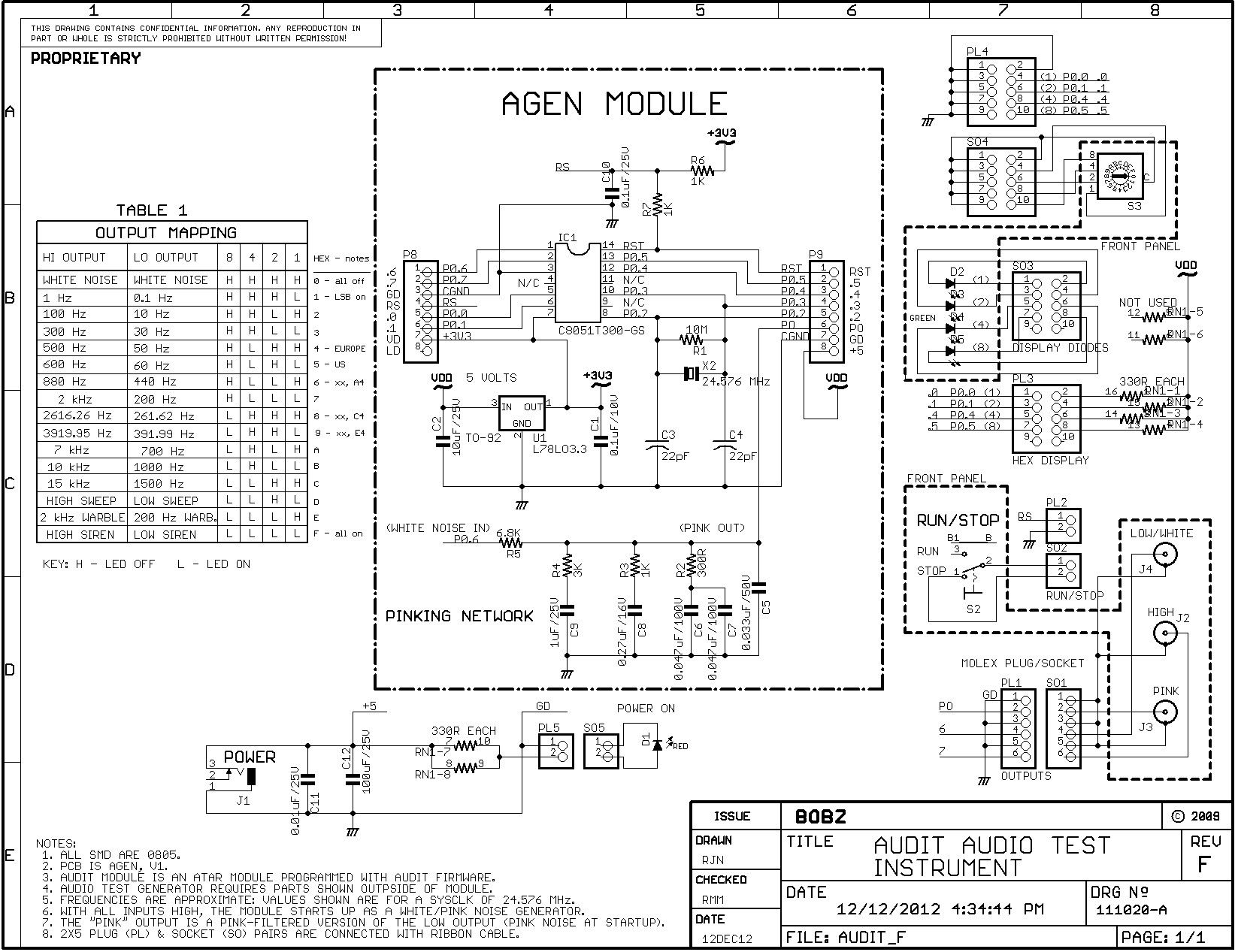
Also refer to the AUDIT audio test instrument described in the Projects section. The instrument described there uses an AGEN to implement a simple and inexpensive audio test instrument. The AUDIT instrument is used to test each AGEN before shipment.
Page 4
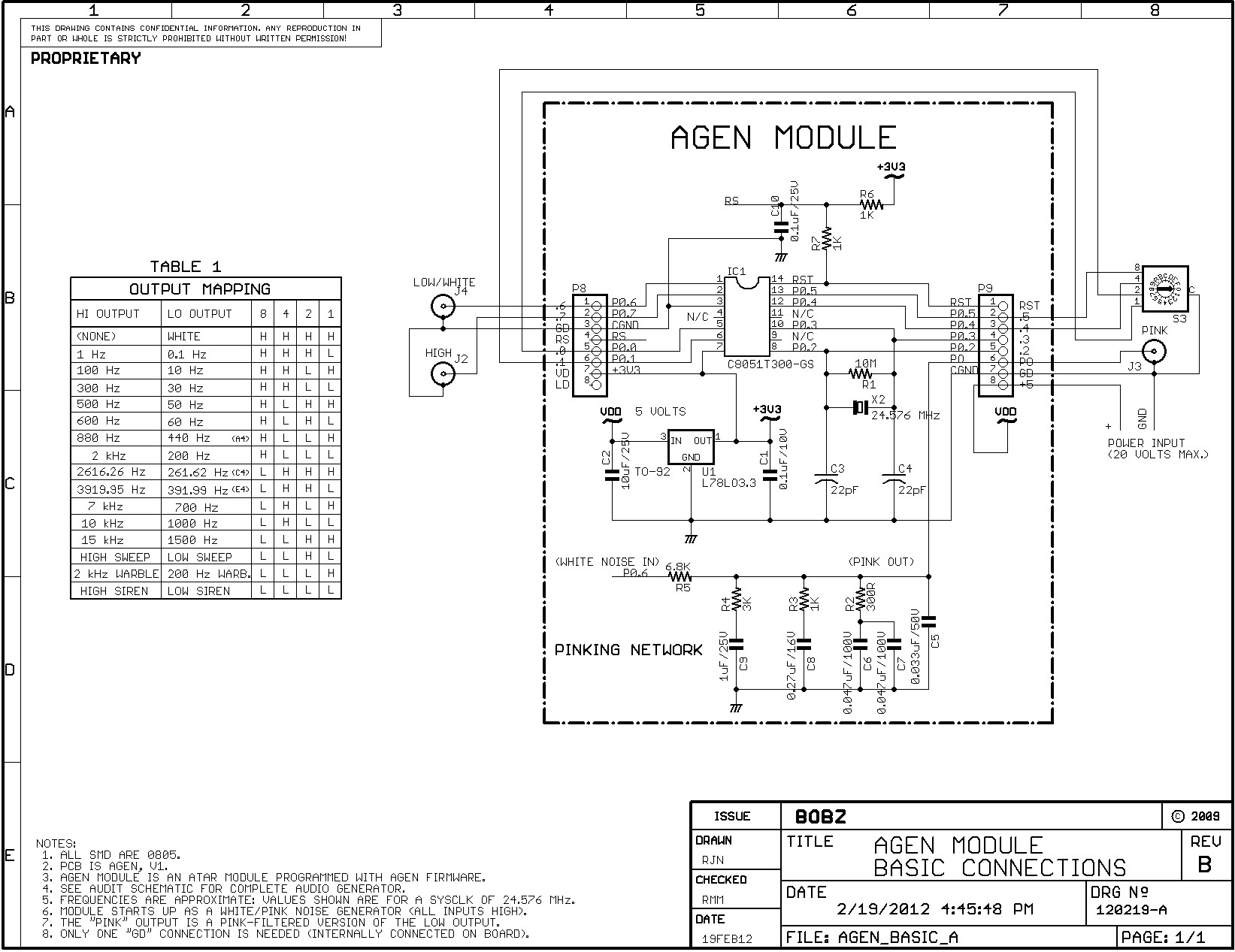
For the following, refer to Schematic 2 titled "AUDIT AUDIO TEST INSTRUMENT." The schematic shows the components, circuitry and pinouts for the AGEN Module. It also shows how the module is wired to produce the AUDIT audio test instrument.
You can also download AGEN schematics in a zip file.
The schematic includes a table that shows what outputs are available for various input pin wiring options. There are four inputs that are functionally coded so that they can be treated as a single hexadecimal digit ranging from $0 to $F. This allows the inputs to be hard-wired for a single function (e.g., noise generator) or user-selected with a hexadecimal-coded rotary switch.
Table 1 in the schematic also provides a bit-by-bit binary representation of the 16 test options. Thus, the hexadecimal digit "$A" corresponds to a binary-coded input of "L H L H" in the table. This indicates that, if the processor inputs for port bits 5, 4, 1 and 0 are wired low, high, low and high (respectively), then a 7 kHz square wave appears on the "HIGH" output and a 700 Hertz square wave appears on the "LOW" output.
The table also provides a quick overview of the available functions and their indications. Observe that most of the table functions consist of a square wave tones at logic levels. For these square wave tone outputs, the HIGH output (".6" on the module) provides the highest frequency and the LOW output (".7 on the module) provides a signal that is generally one decade lower. One exception to this is the 880 Hertz HIGH output: the LOW output for this tone is 440 Hertz (a concert "A" musical note).
Other HIGH outputs were also selected so that their scaled-down LOW outputs correspond to musical notes. For example, the HIGH output at 2616.26 Hertz, when divided by 10, produces a square wave very near middle C (C4). Similarly, the 3919.95 Hertz HIGH output divides down to a frequency very near a "G" note (G4). The HIGH outputs do no correspond to musical notes but are close to 3 kHz and 4 kHz to provide additional tone coverage in the range of 1 to 10 kilohertz.
Generally, the single frequency outputs were selected to cover most of the audio range without duplication. The table below shows all of the freqencies that the AGEN Module can produce and the corresponding hexadecimal input coding. Additionally, the table lists the test functions, such as white and pink noise, that the module can produce.
Page 5
| Same white noise as produced by the NOIZ module | |||
| Same pink noise as produced by the NOIZ module | |||
| Lowest AUDIT frequency | |||
| 10 Hertz is also the first LOW Sweep frequency | |||
| First frequency | |||
| Also the lowest HIGH Sweep ($0D) frequency | |||
| Third frequency | |||
| Also the second HIGH SWEEP frequency | |||
| Fourth frequency | |||
| Third frequency | |||
| Fifth frequency | |||
| 200 Hertz warble tone with $0E, LOW output | |||
| Fourth frequency | |||
| C4 musical note (middle C) | |||
| Sixth frequency | |||
| E4 musical note | |||
| A4 musical note (concert A) | |||
| fifth frequency | |||
| Lowest "French Siren" tone | |||
| Seventh frequency | |||
| highest "French Siren" tone | |||
| Sixth frequency | |||
| Eighth frequency | |||
| Seventh frequency | |||
| 2,000 Hertz warble tone with $0E, HIGH output | |||
| Ninth frequency | |||
| Eighth frequency | |||
| Tenth frequency | |||
| Ninth frequency | |||
| Eleventh frequency | |||
| Tenth frequency | |||
| Eleventh frequency |
Page 6
Because the module replaces the NOIZ Module, it has both white and pink noise outputs. These outputs are generated with the same code as NOIZ, but the highest white noise frequency is now determined by the crystal clock frequency. This is determined by a 24.576 MHz crystal and is close to the internal processor clock frequency used for NOIZ (about 24.5 MHz). For photos of the white and pink noise outputs, refer to the documentation for the NOIZ Module .
All processor port pins are available at the two 8-pin edge connectors, as are power input (e.g., 5 Volts), power out (3.3 Volts) and reset.
A footprint for an optional external HC49/US crystal and its support components are provided below the chip. The crystal oscillator pins (P0.2 and P0.3) are brought out to edge pins. One of these pins can be used for an external oscillator input (e.g., with a 600 chip) or both pins can be configured for general purpose I/O if the crystal or other oscillator options are not used.
The Test/Programming board provides LEDs and limit resistors that can be used to test AGEN I/O pins that are configured for push-pull operation. The AGEN board pin labeled "LD" may be left open or wired to power or ground. When left open, the test LEDs do not load the I/O pins to which they are attached. Wiring the "LD" pin to either a supply voltage or ground allows the port pins to be tested in either "sourcing" or "sinking" modes (ground to source, power to sink). Note that the schematic shows the test LEDs in the "sinking" configuration (connect "LD" to +3.3 Volts). To change to a "sourcing" configuration, reverse the diode polarities and connect "LD" to ground.
Although the capabilities of the microprocessor are beyond the scope of this documentation, port pins are capable of sinking up to a maximum of 100 milliamperes when configured as push-pull outputs (also refer to the Operation section).
When the function pins are set to $0E, the high output will produce a warble tone centered on 2,000 Hertz. The low output will produce a warble tone centered on 200 Hertz.
When the function pins are set to $0D, the high output will produce a series of eleven frequencies, starting at 120 Hertz and ending at 30,720 Hertz. The low output produces a lower sequence of tones, starting at 20 Hertz and ending at 10,240 Hertz.
When the function pins are set to $0F, the high output will produce a "French siren" sound consisting of two alternating tones of 635 and 912 Hertz. The low output produces a version of the siren that is an octave lower, varying between 317 Hertz and 456 Hertz. The tones were originally selected to be in a ratio of 5 to 6, an untempered minor third, as given in Wikipedia. The upper tone was increased to 912 Hertz based on a suggestion elsewhere on the Internet. This does sound somewhat better than the 635 Hertz and 762 Hertz tones needed for a 5/6 ratio.
Page 7
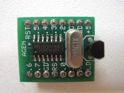
To set up the completed module for operation, it is necessary only to supply it with power.
![]()
Once supplied with 5 Volt power between the "+5" pin and the "GD" (ground) pin, the module can be used with your application. Also see the Quick Start section above.
The output functions described above are selected by applying +3.3 Volt logic inputs to the module, as described by Table 1 in Schematic 1.
To change to the selected function, reset the processor by momentarily bringing the "RS" pin low (e.g., using a momentary contact switch).
Function changes can also be performed automatically with discrete circuitry or a microprocessor. In this way, the outputs can be periodically turned on and off with a timer. Under microprocessor control, the functions can be changed by changing the option pins and the generator can be switched to the selected function by cycling the "RS" pin.
The AUDIT project description provides additional operational information for users wanting to manually control the AGEN functions with switches and indicators.
Page 7
Refer to the documentation for the ADEV Development System for the AGEN parts list. Refer to the documentation for the AUDIT Audio Test Instrument for the parts needed to build an audio test instrument and enclosure.
original circuit with AUDIT Module, Revision D of the schematic |
||
revision E of the schematic, changed references to ADEV vs. AGEN. |